|
|
Being good Aligned is an issue to consider. The normal procedure after changing the rear
wheel is that we first start by aligning the wheel in the driving direction. This is usually the only we do when we align
the rear. The alignment of the bevel box sprocket with
the rear wheel sprocket is nevertheless equally important. Due to the slightly too long bevel box,
there's little space between the swing arm and the Bevel-box on the Port-side
for proper centering. The Bevel-box is placed too far to port. Even after aligning the rear wheel in the
driving-direction, these two sprockets are most of the time still not
properly aligned. After a while driving a misalignment is
created too, which we are trying to prevent by using a lot of Torque on the
Rear wheel spindle nut in the hope it will not move anymore. When you decide to priorities the sprockets
alignment above the wheel-driving-direction alignment you create some wear on
the tire surface, but that wear is negligible compared to the wear on the
drive belt and the noise it creates against the sprocket walls. I have driven over 11.000 km with this system
and I cannot find a reason why to renew my rear-wheel tire which is actually
not exactly ( < 1 cm ) in the middle of the trike. And steering is
balanced too. Experimenting to find a better alignment
option. An issue we encountered during our successful
‘Reconditioning Bevel-Box project’ - https://www.talkmorgan.com/ubbthreads.php/topics/833650/the-reconditioned-bvel-box-project-is-finished - was the alignment between Bevel-box and the Rear-Wheel. Which is also a noise issue. And not specifically important for the choice
between Belt-driven or Chain-driven. Both options give typical problems when
not good aligned. With the Belt-drive the issue is even more
seriously and main cause of the squealy belt noise which is common for most
belts rubbing alongside a sprocket wall. With Phill Bleazey ( PB ) chain drive
conversion kit, you have more possibilities to align the sprockets better
because of the rear-wheel sprocket system. We believe this issue is seriously
underestimated, and we've experimented with several modifications to address
them. We tried to find a solution, but - like
always with our M3W - a project like this takes a lot of research and
development time. Phill Bleazey ( PB )
gives a very clear explanation in one of his very well made You-tube
videos. See the 7:30 mark for an explanation of the
alignment issues. When not perfectly aligned over the two
sprockets the Drive-belt runs to a side of the sprocket – to improve by
itself the alignment - and will shave for this reason along the sprocket
protection wall. The chain is far more flexible in this, but
still creates extra wear and tear on the sides of sprocket teeth. In both cases it creates extra noise and extra
wear. So we looked to an improvement. I.
Bevel-Box alignment. We found that our NVH kit is actually quite
well aligned, but seeing the many differences between all the M3W that’s not
a guarantee for all other Morgan 3-wheelers. And even mine could be better made. My
NVH-aft-part is miss aligned with around 2 mm sideways. And – as nicely
explained by PB - at the rear wheel
this will result in a huge factor more. Who cares ? I do. And not only for the noise reduction. We opted for PB’s Bevel-box
support/mount. After a year driving with the ‘PB-Bevel-box
mount’ we found that side-way pressure on the Bevel-box increases
miss-alignment. The reason is simple. The Belt and to a lesser extent – because of
lesser tightness of a chain compared to the belt - pulls the aft part
at Port-side of the bevel box sideways. The aft part of the NVH kit will stop this,
but the PB mount cannot really stop this, the friction of the PU-layer is not
great enough. That’s a pity because the ‘PB-mount’ has more Pros than Cons
compared to the NVH kit. So we experimented with solutions and came to
a – self hand-made - simple but light and strong device bolted to the aft
part of the PB-mount and with a long M8 thread to the old Starboard NVH-kit
mount. Using some nuts on that M8 thread you can get
an exact alignment of your chain and of your belt at the Bevel-box. With a chain-sprocket the alignment is very
simple to find, because you just look upon the Bevel-Box-sprocket hub and the
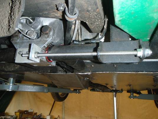
chain and you will see clearly the exact alignment. With the belt it is slightly more complicated. Picture of Bevel Box alignment device.
See our air-duct in front of it at the bottom. II.
Rear-wheel alignment - Already Published on TM : 2024-03-15 #797606 improved, but I like to describe the
results after over 11.000 km use. Aligning the belt fixed on the Bevel box
sprocket is of course not enough. You have the problem of not having an always
fixed and simple designed alignment of the rear wheel, which stays fixed and
will not move. A lot of owners just make a quite good guess
of the alignment and after that they put an extreme lot of torque on the
rear-wheel spindle-nut and hope ‘for the best’ that the rear wheel
never moves again sideways. That is of course not a good solution and will
never work properly. We found that every alignment of the rear
wheel on our M3W after a while was changing a little. Typical, we always found that the
Starboard ‘aft’-adjuster was loose after a while when the spindle is
moved backwards at that place. It only pulls, but does not push. And really every 1 mm mis-alignment at this
place counts, especially for belt-drives. See again PB’s video. Any improvement should not be found in a
massive force on the nuts but on an extra rear-wheel alignment device, an
extra adjuster to pull the rear-wheel spindle forwards.. We studied how this problem have been solved
by contemporain motorbike designers and we found that no modern bikes do have
only ‘aft’-adjusters. “Only having ‘aft’-adjusters is really
1940th ” I had them for the last time on my ‘WWII
Harley Davidson Liberator’ in the 60th and to my surprise now again on a 2011 M3W [ Vin letter ‘B’ ]. Motorbikes have even 1 mm alignment marks on
the swing arm to find a really neat adjustment and with a ‘Forward-adjuster’
you never need to change this alignment again. So we designed in March 2024 also a ‘Forward’
alignment device or ‘Forward’-adjuster which blocks the spindle moving aft.
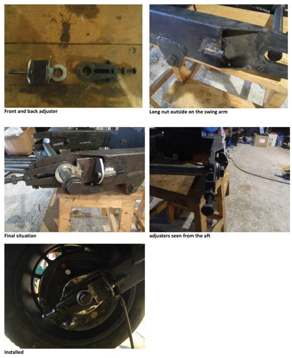
And also blocks any movement forward, by using an extra blocking nut . Experimenting we welded first a long nut to
the Swing arm to connect it with a grade 8 bolt to the adjuster, but are
making now a new one which we can bolt on the swing arm. In that case it is
not necessary to take off the swing-arm for a welding job. The swing arm is hollow at this spot so you
can easily drill some holes and bolt the ‘Forward’-adjuster on it. We found that actually the ‘Forward-adjuster’
on the starboard side of the swing arm is the most important. Logic of course
because at port side the wheel is pulled forwards by belt an chain and that
should be stopped by the already existing ‘old fashioned’ rear-wheel
‘aft’-adjuster. Still we use two of our ‘Forward’-adjusters
because of easier handling of the heavy rear-wheel and to get an even better
fix.
Pictures during experiment phase. Currently we have used a nearly 6 mm thick
aluminum plate for the ‘Forward adjuster’ and the welded bolt is now welded
on a separate plate, which we can mount on the Swingarm.
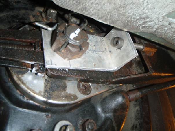
Picture of the new (2026) rear wheel starboard
‘Forward’ alignment device. A blocking nut is forward of the upstanding
wall placed to fix the bolt. So the ‘Forward adjuster’ works also as a
supplement for the existing rear-adjuster. When installing two Forward-adjusters we a use
shorter M24 crown-nut. ( The orange color is linseed oil which I use
a lot on metal ( and wood ) to protect) Installing the wheel Installing the wheel and aligning it is now very simple. You take temporarily away the two suspensions. The long nut of your first Forward- adjuster - with a 70mm M8
bolt - is turned in. And will stay there for ever. Taking the rear wheel out is simply taking only the spindle out. The
spindle castle-nut at Starboard. The rear-Wheel in. You place the rear-wheel between the two swing arms with a jack to
lift the wheel until the spindle holes are free in line with the adjuster
holes. Put the spindle in from Port-side. And the wheel is secured and you
can start aligning the wheel. Actually you probably have already the right alignment now, as long as
you did not change the bolts on the adjusters. The rear wheel cannot slide out anymore. You do not need the spindle
nut firmly tight at this stage. When you do it for the first time, you fix the ‘Forward’- and
‘Aft’-adjuster bolts with their separate blocking nuts. They are forward
against the vertical part of the 90ᵒ slider. And ready. Now you can turn the spindle nut tight. And finally place the blocking pin or a piece of steel wire at the
spindle castle-nut in the shaft. And bring the suspension back in place. You do not have to use extreme Torque on the
nuts again. You just use - like for every small car wheel
bolt – a torque-force of around 70 ft/lbs
and 95 Nm. I am using now a 35 cm length Bahco wrench. Before I had this adjuster, I needed an 110
cm extension attached on it. The front new ( 2026 ) developed ‘Forward’-adjuster is actually much
stronger than the MMC aft adjuster. In fact - like with most modern motorbikes ( Most of them do have only front
adjusters ) - Actually I do not
need anymore the MMC ‘Aft adjuster’ because of the blocking nut I use at the
front wall of the Forward-adjuster. Nevertheless I am still using the aft adjuster to push the
spindle/shaft back because it is useful when aligning. Using two the new developed ( 2026 ) ‘Forward’-adjusters we have to use a shorter
Castle-nut on the spindle. It took some find to find them on the internet. To my surprise I saw in a post on TM - https://www.talkmorgan.com/ubbthreads.php/topics/797312/rust-story-on-the-new-super-3 - that MMC in 2023 still uses only the same old
fashion not so adequate aft-adjusters. There is an extra little present by installing
this forward adjuster. Changing the rear wheel, I could not really
handle it. The wheel is too heavy for me and can fell out of my arms
and is also too heavy to keep it easily well-aligned in place when putting
the wheel in again. With a jack just under the wheel and two new
‘Forward’-adjusters you only remove the spindle and the rear wheel does
not drop down uncontrolled when changing the rear wheel. More luck you have when you put the wheel in
place again and pushes the spindle in. You are actually ready. No fuss with new alignments or tightening the
spindle-nut tighter than is good for the thread and nut and which still will
change - after a while - the alignment you thought was OK. Only when other people work on it for the
first time I recognized they are confused, but it is quickly learned. The alignment stays ( nearly ) exactly as it
was. |
|